Conversion from an elevated radial design to a conventional in-ground mount. 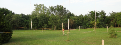
The 40m 4-square was the first antenna built when I moved to this site. It was quick and easy to use an elevated radial system (pictured at right). Over the years the 4SQ has been one of my favorite antennas but the elevated radials require care and are difficult to mow under. And this year I noticed that some of the 4x4 support poles had started to show cracking with one breaking. With the main tower work complete, this looked like a good time to overhaul the 4-Square. The 40m 4-Square System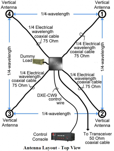
A 4SQ is a set of 4 verticals and a controller box. The physical layout and the phasing action of the controller give the system the ability to point in one of 4 directions as well as an omni-directional mode. Typical performance characteristics of a 4SQ system: - Gain: 5 dBi
- F/R: 20 dB
- Beamwidth: 90 deg
- SWR bandwidth: under 1.5:1 across band
4SQ systems find favor in low band situations where the physical issues of a yagi are significant. The 4SQ with it's 4 sets of verticals is a simpler challenge by comparison, especially on 80 and 160. The tradeoff is primarily in required land area for the verticals and their required radial fields. The 40m 4SQ is about 105' x 105' for example. 40m Beam and 4-Square SynergyThe 40m beam generally has better signal strengths compared to the 4SQ. However the beam must be physically moved to change directions where the 4SQ can be "rotated" instantly. The combination of the beam and the 4SQ are an excellent combination because the 4SQ's strengths address nicely the beams' weakness. In domestic contests the omni direction mode of the 4SQ works almost as well as a dipole. In DX contests, I would normally run with the beam pointing NE and then jump to the 4SQ if the caller is weak and from some other direction. The 4SQ also is an excellent mult antenna for chasing a SA or JA spot that pops up without having to swing the beam. The Spacing Question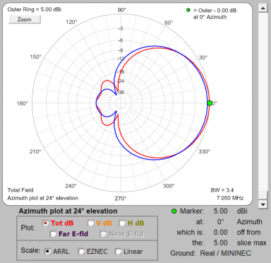
The array was built 42' per side. The length used was actually a mistake - I had intended to use that as the maximum spacing and then pick a shorter length based on modeling. But the guys making the holes drilled at the 42' spacing and that is what I was left with. Fortunately it worked out fine as the CATV 75 ohm hardline had a very high VF enabling the physical connection from the vertical to the controller to be physically made. At right is an AZ comparison of the standard 35' (BLUE) and 42' (RED) spacing. The gain in the 42' case is slightly higher owing to a bit more narrow beamwidth. Response off the back is about the same in both cases with a bit more response in the 125 deg heading offset in the 42' case. 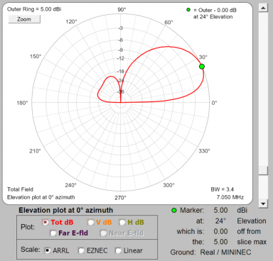
Elevation plot - 42' spacing. Gain numbers reflect expected real-world gains based on the full model of both the antenna and the combiner realized in the comprehensive AutoEZ 4SQ model from AC6LA. 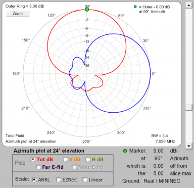
At 45 degrees offset, the signal is about -3 dB. Beamwidth in the 42' case is slightly less compared to the 35' case so the 45 degree offset strength is about 0.5 dB less. Ground Support Poles and Vertical Mounts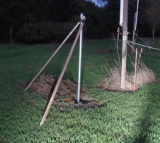
Holes for the 10' 2" water pipe (2-3/8" OD galvanized steel) posts were dug with an 18" auger and were about 4' deep. A few inches of gravel around the bottom of the pipe followed by a couple of bags of post cement. Tops of the poles were secured with two wood brackets allowing for easy trim of vertical on the pipe. After a couple of days another 5 bags of redi-mix concrete filled the holes up to within a few inches of ground level, and then topped off with soil for the finish. 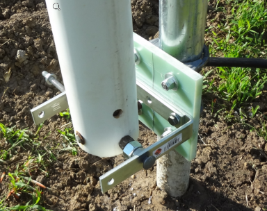
Brackets to attach and insulate the verticals were made from 6x6x1/2" G10 fiberglass material. 2-1/2" saddle clamps hold the fiberglass to the in-ground pole. And some 6" utility brackets and long bolts hold the vertical to the bracket. Eventually the verticals will be replaced and having no idea of what the final size will be, this configuration using the utility "L" brackets provides adjustability and is cheap. The bottom bracket also serves as a hinge for easy lowering of the vertical without requiring disconnect of the feedline jumper. The top bracket is mounted to the pole and takes advantage of the other two holes in the utility bracket. Not shown here is a plastic insulating sleeve and bungee which keeps the vertical from rubbing on the retaining bolts in the winds. This will be fine until the verticals are replaced. And like the bottom bracket, provides plenty of flexibility for the final configuration. To lower the vertical for repair or adjustment, just pull the outer bolt and walk the vertical to the ground. Slick! 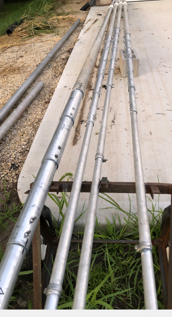 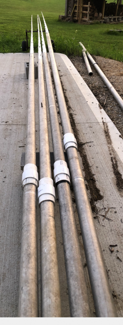
The element construction shown here. Bottom sections are 3" OD 1/8" wall tapered to 1-1/2" by some DXE tubing cut to short lengths. The rest of the run is built out of Hygain 20m 206-series beam elements. Wind simulation using the DXE Yagi Mech tool showed 85 MPH survival in the horizontal configuration. No idea how that translates to the vertical case. Radial Field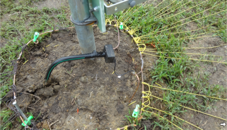
Each vertical has about 50-60 radials averaging 40' in length. A #6 copper ring was tacked in place with some tent stakes and radial wires tied to the ring. They were soldered to the ring in groups using a MAPP torch and solder. The 75 ohm runs are made from 5/8 CATV hardline and fitted with PL259 on each end. A breakout block of a SO239 set in epoxy splits the two conductors of the feedline with one running to the vertical, and the other to the ground ring. The far end of the radial is held in place with a lawn staple. 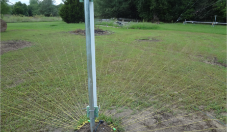
A view of the NW vertical field. Radial wire was #18 insulated stranded copper with PE insulation. About 10,000 feet were put down in 4 different colors. The yellow color of one reel is easy to see laying against the grass as shown here. But the other colors used (brown, green, blue) are difficult to see even before the grass stars to grow and pull them down to the grass mat. I will let the grass grow a few weeks until it's tall and then cut it high for the rest of the season. By next year the radials will be fully incorporated into the grass and invisible. OMNI-mode SWR ModificationThere is one downside to the adjustments in element spacing and phasing line lengths - the OMNI mode SWR was pretty high when measured on the completed array. This normally would not be a problem for tube amps but as I had reciently added a SS amp to the lineup, it was a problem; the SS amp was not happy at all about being asked to drive this load. 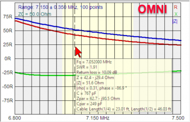
The DXE controller provides an OMNI mode function using relays which tie the 4 elements in parallel, and bypass the hybrid network completely. A LC network inside the controller matches the 50-ohm feedline input to the paralleled elements and under the DXE-recommended spacing, the OMNI mode provides a nice match. Measuring the L/C network values the expected load is about 14+12j. With the 4 elements joined together through short jumpers, the measured load presented by the actual array was 22+18j. Shown at left is the measured response of the box with the antennas attached and with the stock DXE match. 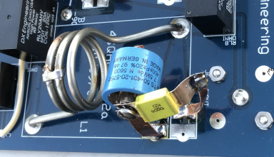
The DXE network is built from a series 0.3 uH inductor and a shunt 750 pf. To get a good match to the 22+18j, the correct L/C network would be about 0.15 uH + 500 pf. I removed the 500 pf SMT chip cap first, and then shorted turns on the coil while measuring the resulting L value. Fortunately shorting two of the turns provided a value prety close to the 0.15 uH needed and I soldered that in place. Next a 500 pF cap was built from a 400 pf doorknob and a 91 pf transmitting cap of unknown orign pulled from the junk box. Circulating current is going to be high in this kind of network so low ESR caps are best (hence DXE's wise choice of the MLCC SMT chip cap) but that's what I had and with bad weather approaching, I tacked those to the board. 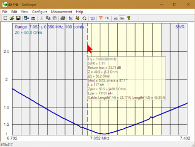
To test the match on the bench, I put a 22 ohm resistor and small inductor to simulate the +18j and the SWR as measured on the input to the net was very nice. The controller was mounted back out in the field, cables connected and the SWR response measured with the result shown in the plot to the left. The Finished 4-Square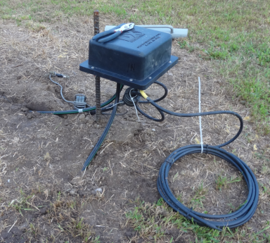
4SQ controller from DXE shown here with a couple of the vertical feed lines extending from the ground. The stub attached is a 20m notch to provide 2nd harmonic suppression. The control line and the feed line from the transmitter both have chokes made from type 31 ferrites. Unlike the elevated implementation, there are no separate common mode chokes on the vertical feed lines relying on the magical attenuation of the ground to serve the purpose. A view of the finished 4-square with the 40m tower in the background. 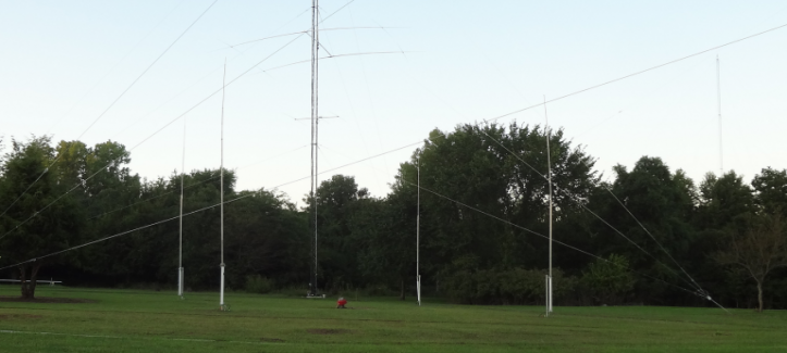
|