The rig of my youth joins the hybrid lineup As a kid, the first modern radio I owned was the Kenwood TS-520S. When I went to college I sold it to the manager of the dorm I lived in and never looked back. Almost 40 years later a a nice looking unit came up for auction locally and I managed to pick it up. The tweaks to that unit and some other comments about the rig's performance are detailed below. To get the rig ready for the lineup, these 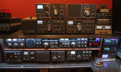 mods and adjustments were made on the TS-520S : mods and adjustments were made on the TS-520S : Alignment A check of the MDS showed better than -130 dBm on all bands. So the only adjustment that was done involved the SSB/CW carrier oscillator adjustment and the calibration oscillator. A purist may suggest doing the full alignment would be good as a general principle but touching the 40 year old adjustment slugs is not a risk free operation so my approach to these old rigs is to fix things that are broken, and to leave what's working alone. Filter ResponseReceiver passband response was measured in each mode and the graphs look like this: 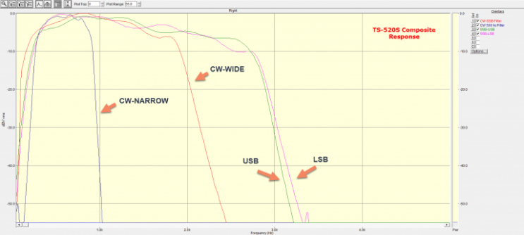
The Kenwood default sidetone is 800 Hz but I prefer a lower 600 Hz or so note. Fortunately on this rig the filter is off center a bit to the low side and even I only had to cheat on the carrier oscillator to center the response around the lower value as a result. Upper and lower response is nice and essentially uniform. External Amp Switching FETTo avoid any risk of hot switching my amp's expensive and difficult to replace vac relays, I add a MOSFET that is driven off of the same line that drives the rig's T/R relay. The amp has a very fast relay (~5 mS on close) and the combination of MOSFET relay on the hybrid side and the vac relay on the amp side means that the amp is 100% ready for transmit power and essentially is waiting for the RF to come up on the transmitter. The down side of the FET switch is that it would also drop the amp line faster than the relay would close on the transmitter however using semi-breakin on the hybrid ensures that the amp relays remain engaged well after the rig moves to receive. 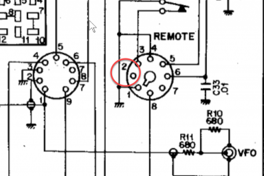 Adding the FET is easy in the 520S thanks to a conveniently located and unused pin on the remote jack. I used a 600V 10A MOSFET from my junkbox which was in a TO-220 package. Adding the FET is easy in the 520S thanks to a conveniently located and unused pin on the remote jack. I used a 600V 10A MOSFET from my junkbox which was in a TO-220 package.
The FET connection points are: Source - REMOTE JACK pin 1 (grounded) Drain - REMOTE JACK pin 2 (unused - see schematic) Gate - RY pin on Generator Board (white/purple wire adjacent the HV cap mounting points) The FET requires no heat sinking and the TO-220 package leads are very rigid so the device is self-supporting on the leads alone. It's somewhat protected in it's mounting point from the surroundings as well 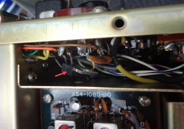
Quieting the Relay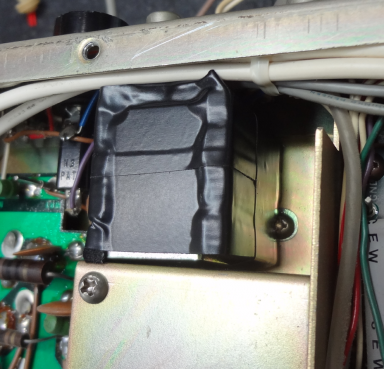
The relay in the TS-520S is not very loud but its noise level can be damped significantly by packing some sound-absorbing material around the RF shield. In this case I used some small lengths of 1/8" thick weather stripping and then over-wrapped with Scotch 33 tape to make sure the strips stayed in place. CleaningInternally the rig was immaculate. Externally only a bit of accumulated dust and grime was found on the knobs. Some soap and water restored the face to a near-new state. And fortunately the clear bezel was flawless as well. Replacing Bulbs with LEDsPersonally I do not like the "classic" glow of light bulbs on older gear over a retrofit of modern (and nearly infinite life-time) white LEDs. With most rigs that involves adding some LED above the meter and then replacing the dial illumination bulbs with an LED. The trick with this sort of modification is to diffuse the naturally point-source LED light so that the resulting light is spread over the meter and dial evenly. For the TS-520S meter, I used white electrical tape on the top edge of the meter bezel. And sandwiched a trio of LED on a strip between two clear bits of scrap plastic. The combined thickness of the plastic + LED was just enough to fill the space between the top of the meter and the bottom of the metal bracket that supports the meter. 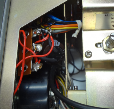 For the dial lighting, a similar 3-led strip was secured over the PCB that holds the 3 red function lights. The Kenwood front cover bezel has a silvering on the inside and using a bit of hot glue to point the LED strip slightly down resulted in a very nice looking result. For the dial lighting, a similar 3-led strip was secured over the PCB that holds the 3 red function lights. The Kenwood front cover bezel has a silvering on the inside and using a bit of hot glue to point the LED strip slightly down resulted in a very nice looking result.
Power for the LEDs was pulled from the +12V AC line that fed the original bulbs. The LED strips can be run directly from the AC line but the brightness and flicker is not pleasing so I added a single diode and filter cap to the header and that provided a nice 11V DC feed for the LED strips. Kenwood Recommended ModsThere were two mods done based on Kenwood service documents. One was adding a small jumper from a crystal to a coil shield on the carrier oscillator board (CW frequency shift fix). And another was putting a series resistor in line with a +6V feed wire to the bandswitch (prevents shorting the supply line moving between 80/40). CW Fitler SwitchA Kenwood suggested modification that retasks the fixed frequency switch to serving as a CW wide/narrow switch was done by the prior owner. The Final Result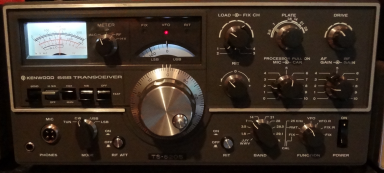
Love this radio. Sounds great. Works good. And looks fabulous while bringing me magically back to my youth every time I fire it up. If you catch me rag chewing on 40m, there's a good chance this is the radio you would catch me on. 73/jeff/ac0c | 