 Building a flexible AVR hardware test solution with basic instrumentation Building a flexible AVR hardware test solution with basic instrumentation
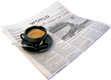
This system is based on the Mikro EasyAVR6 development board. Some features are built into the development board like LCD, LED, switches, AVR programmer interface, graphic LCD, serial LCD, bus expander and RS232 interface. What I've done is to take this and add to it basic instrumentation and a breadboard area. The idea is that the board makes it easy to test out software developed for an AVR chip without requiring the hardware to do the test be breadboarded as a seperate project. For more details on the Mikroe EasyAVR6, look here: http://www.mikroe.com/eng/products/view/321/easyavr6-development-system/ CONSTRUCTION DETAILS The EasyAVR6 is mounted on a plastic backing which further serves as the basing structure for the rest of the added components. From left to right, the LCD oscilliscope, the oscillator module, and sitting on top of the breadboard area, the DVM/frequency counter module (which will eventually be mounted to the right of the oscillator. The space between the oscilliscope and the oscillator will eventually hold a general purpose IO board with switches, speaker, rotary encoders, etc. The entire combination - along with the breadboard accessories - provides the basis for a complete test system. 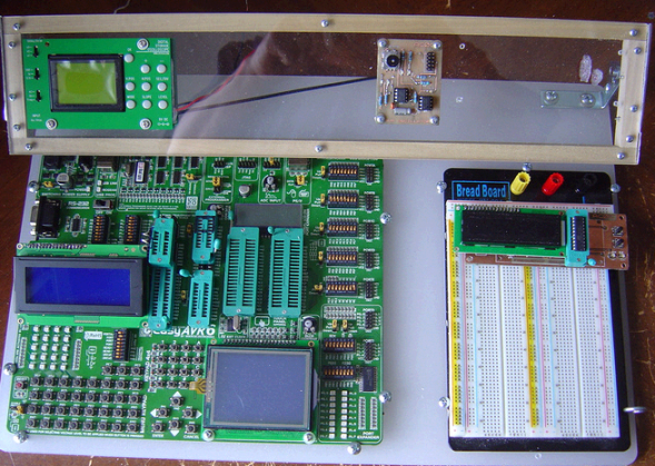
The board has pressure based sockets which are fine for casual use. But for serious work, a ZIF is needed. Unfortunately, the spacing provided does not quite work out properly given the oversized needs of the ZIF socket. So some creativity was needed to get sockets to fit. 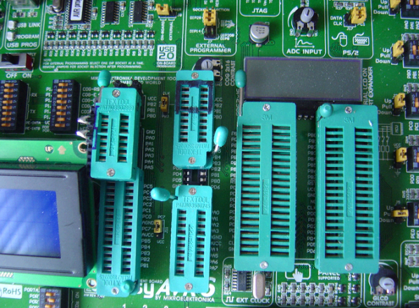
Instrumentation added is both commercial and home brew. To the right is the DVM frequency counter module. Two seperate voltage inputs provide 0-15V range. For AC signals it will display P-P. The frequency counter input can look at the oscillator module, or can be fed from a probe point in the traditional test instrument style. This board is not completed yet from a firmware standopoint. And it will be interesting to see how the counter logic works with respect to the maximum frequency capability. 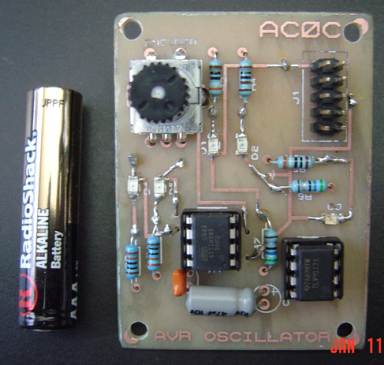
The oscillator board provides high current output in both Q and Q-not polarity. The rotary encoder adjusts the frequency from a range of about 120 seconds period up to about 100 Khz. High resolution is provided around the 600 hz AF filter range and around the 1 second clocking range. Frequency can be read by the DVM above. Or the user can cycle between 3 preset frequencies - 1 hz, 600 hz and 100 Khz - just by pushing down on the rotary encoder. LED's on the board indicate the status of the outputs as well as providing a visual feedback of rotary encoder revolutions. The most amazing addition is the JYTECH digital scope. This unit sells for just $50 assembled and has the most amazing range of features. It's mounted here flush to the plexiglass panel so all controls are accessable. Has a 1Mhz bandwidth, capable of sample and hold and has a basic spectrum analysis function via a FFT feature. Reads voltage and frequency directly. External trigger. Built in 500 hz 5V test signal. 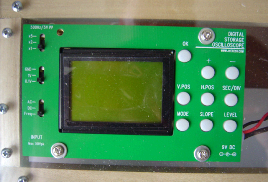
An example of the display here. Just what everyone needs for their lap-top breadboard development environment. 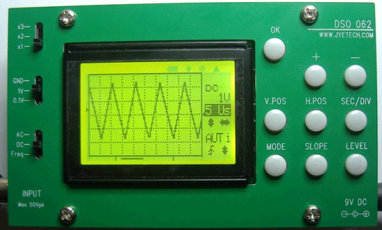
Lastly, the solderless breadboard allows quick prototyping of any circuit. And to help speed up that there are an assortment of accessory break-out board modules covering all the common I/O connectors and some of the common I/O logic like RS232. 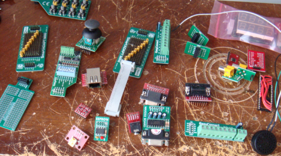
|