Taking a look at the analog side of the FT-2000
One of the great things about the FT-2000 is that the sub RX is a fully analog implementation. There is a school of thought that says a DSP based rig will never have the same crisp and clear sound as a rig with a DSP in the IF strip. That is not a subject that we can resolve here, but a good comparison between the main and sub RX in the FT-2000 would be very interesting. From the Yaesu marketing brochure, this block diagram is helpful in understanding the differences between the main and sub RX. The entire circuitry of the sub RX resides on a separate board, and the buffered line-level AF output is fed to the main circuit board where it shares a common AF amplification path. 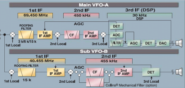
Areas of InterestWith respect to the sub, there are a few characteristics of the sub RX that I eventually want to investigate. These are items that I believe offer some possibility of improvement over the stock configuration. - Differences in the AF response between the main and sub RX, especially on CW. The CW mode on the main RX has a low end roll off which is not present in the sub RX response.
- The RX has a "hiss" sound under weak signal conditions, and with the NAR CW mode especially. With PRE2 engaged, the hiss is almost not noticeable.
- What are the strong signal characteristics of the sub RX? Generally, I am more interested in the weak signal response of the sub RX. So if an optimization requires a choice between better strong signal handling, or better low signal sensitivity, then my preference will be to optimize the weak signal sensitivity.
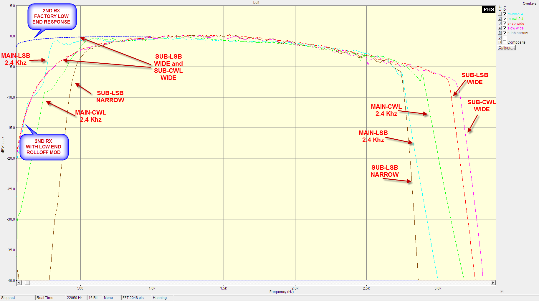
Click on graphs to download full-size clear plots Main RX vs. Sub RX Filter ResponseThe following graphic plots the main and sub response vs. frequency. Observations: - Both receivers has a gentle roll off on the high end. There are 2-pole low pass filters in both AF feed lines with a rough roll off frequency of about 3 KHz.
- The default widths of the main RX are set by the DSP under firmware default, and in the narrow case, menu selectable from a preset list of options. The adjustment options requires a set of constants in a table and their number may be limited by available memory storage space in the firmware flash ROM.
- For the 2nd RX, a set of filters in the 2nd IF are selected by the control unit via firmware between 300/500 Hz (if installed), 1.0, 2.2, 6, 8 and 16 KHz. Actual widths are affected by the signal input level and the circuit details.
- Ultimate attenuation of the main RX at moderate signal levels (e.g. S9) is as much as 90db. The 2nd RX attenuation is 35-70 db, depending on conditions.
- The main RX has a low end roll-off at about 300 Hz in LSB (blue trace) and about 540 Hz in CWL (green trace). The sub RX has no roll off (dotted blue line) in either mode.
- A modification (described below) can provide a similar low end roll off to the sub RX (pink/purple traces).
With this modification, the overall responses of the two receivers is quite similar.
Main RX vs. Sub RX Filter Response - CWL and LSB 
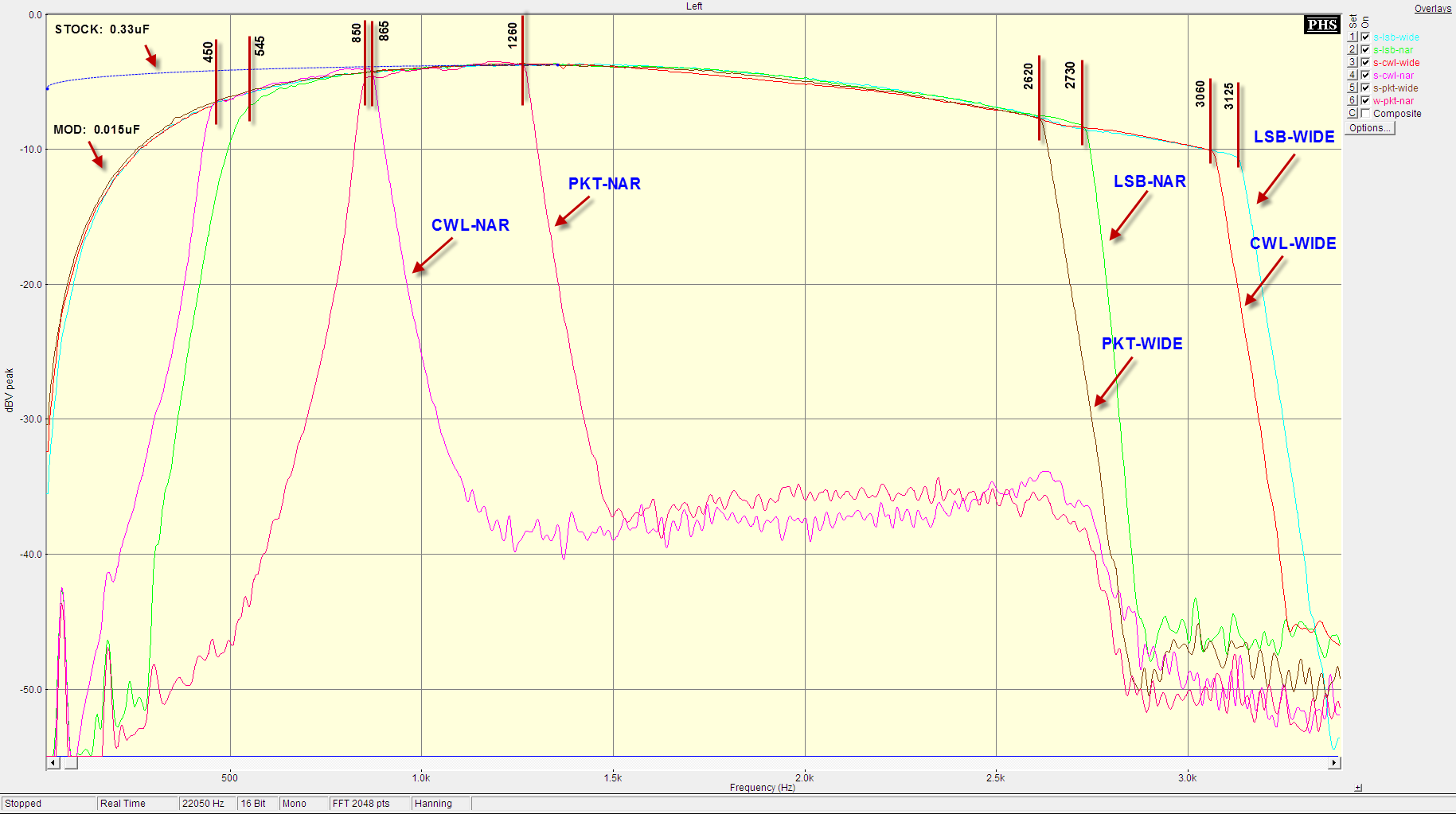
Sub Rx Filter ResponseTo establish a baseline of the 2nd RX performance, I scanned the rig sweeping a S9 input into the antenna terminal, and looked at the resulting peak-response plot from the AF OUT jack on the back side of the rig. Sub RX Amplitude Response - CWL, LSB and PKT Modes - Wide and Narrow 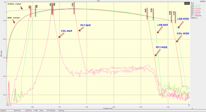
The plot compares the filter response of 3 operation modes, in both the wide and narrow settings. Calculated passband widths are given in the following table: Mode | Filter Mode | Fl @ -1db | Fu @ -1db | Width @ -1db | LSB | Wide | 50/450 Hz | 3125 Hz | 3075/2675 Hz | LSB | Narrow | 545 Hz | 2730 Hz | 2185 Hz | CWL | Wide | 50/450 Hz | 3060 Hz | 3010/2610 Hz | CWL | Narrow | 450 Hz | 865 Hz | 415 Hz | PKT | Wide | 50/450 Hz | 2620 Hz | 2570/2170 Hz | PKT | Narrow | 50/450 Hz | 1260 Hz | 1210/810 Hz |
The bandwidth in BOLD reflects the unmodified (stock Yaesu) configuration - as shown by the blue dashed line in the plot above. The normal lettering (not bold) is the same passband width calculation - with the low end roll-off mod (see below) implemented. Filter selection vs. mode - set by firmware: Mode | Wide | Narrow | Narrow (with add-in) | FM | 15 kHz | 8 kHz | 8 kHz | AM | 8 kHz | 6 kHz | 6 kHz | LSB/USB | 2.2 kHz | 1 kHz | 1 kHz | CW | 2.2 kHz | 1 kHz | 300/500 Hz | PKT | 2.2 kHz | 1 kHz | 300/500 Hz | RTTY | 2.2 kHz | 1 kHz | 300/500 Hz |
Shape Options and Filtering CommentsNotice the shape of the LSB-NARROW response. I would prefer that this mode be the default response for the CW-WIDE because the LSB-NARROW provides a very nice roll-off response on the low end. In this LSB-NARROW mode, the 1 KHz filter is selected, and an IF shift of about +500 Hz applied. The graph below shows the details. For my Yaesu Firmware Wish List - allow setting the default filter choice for the CW wide mode to allow selection between the 1 and 2.4 KHz. The option of using the 1 KHz filter as the CW-WIDE mode would require no hardware modifications as the filter selection is set by the firmware through a 4053 decoder. It looks like a simple hardware mod may be possible in the event an eventual firmware solution is not available. UPDATE: 1K filter mod is complete. Test data further down the page! LSB narrow vs. CWL narrow Modes
Log-scale zoom view of the low end response - includes the low end roll-off modification 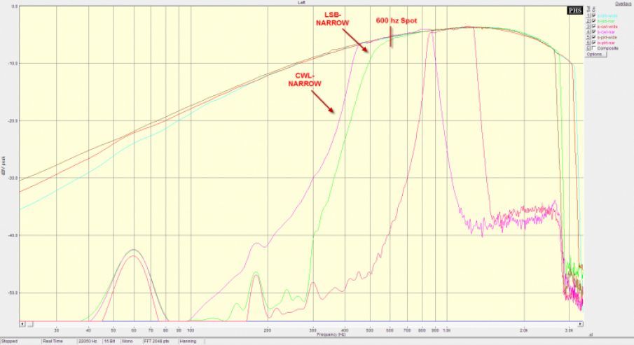
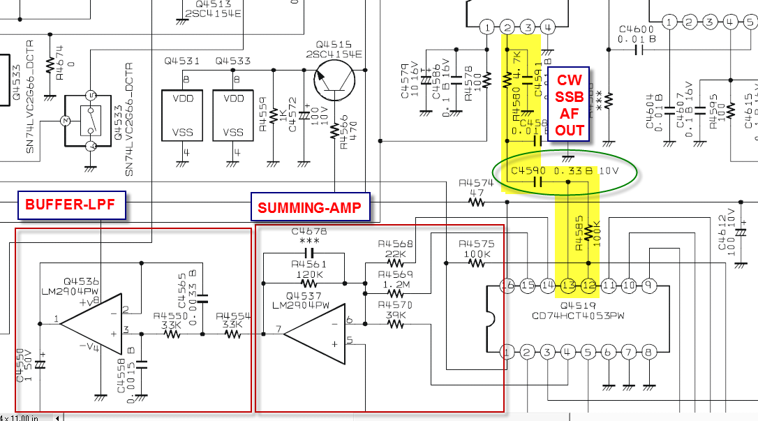
A Mod for the Flat Low End ResponseThe main RX has a nearly flat filter response down to about 50 Hz and then it rolls off in SSB modes. For CW, the main RX DSP action rolls off the response starting about 400 Hz. By comparison, the sub has the similar response on SSB and CW. Extending nearly to zero Hz. My personal preference as a primarily CW op is to have the low end roll off. The low end contains quite a lot of AF energy and is fatiguing in prolonged listening sessions. And even when listening to voice modes, I prefer to have less low end content for the same reason. When considering mods for the rig in general, there is a engineering decision to be made between simplicity vs. effectiveness. So in this case, by changing the value of the coupling capacitor, we can introduce a single-pole roll-off response and see how satisfactory that is in actual use with minimal modification complexity. The response graph above, in the upper left corner, shows the effect of changing one capacitor in the sub RX from the stock value of 0.33 uF to 0.015 uF. Of course, other values would provide more or less roll off in comparison. I also tried value higher and found the 0.015 uF to be the best overall compromise value. There are two minor side-effects to this mod - in the CW narrow mode AF passband, the response has about a -3db "tilt" from right to left. This is not significant in my listening and I prefer to have too little low end, vs. too much. This modification does not affect the AM or FM modes. Mod Details: Adding Low End Roll-offTo implement the similar modification, consider the schematic and PCB drawings that follow. The signal path for all CW/SSB mode variations is through C4520. The rig provides two stages of low pass filtering, first a pi-network (yellow highlight) just prior to coupling cap C4590 - and then a second pole type located at the output buffer amp Q4536 (bottom left red box). Lowering the value of C4590 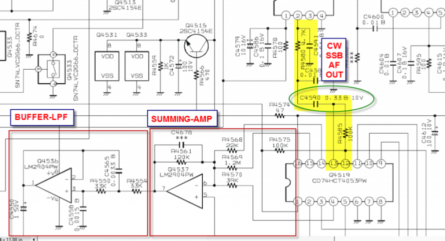
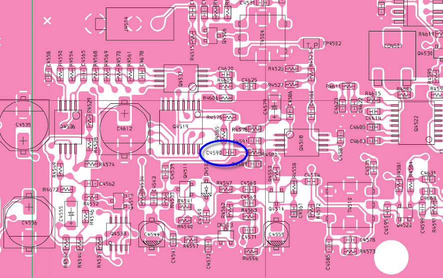
The cap's location on the 2nd RX PCB is here. Part size is a 0603 although a 0804 will fit and is far more easy to handle in practice: 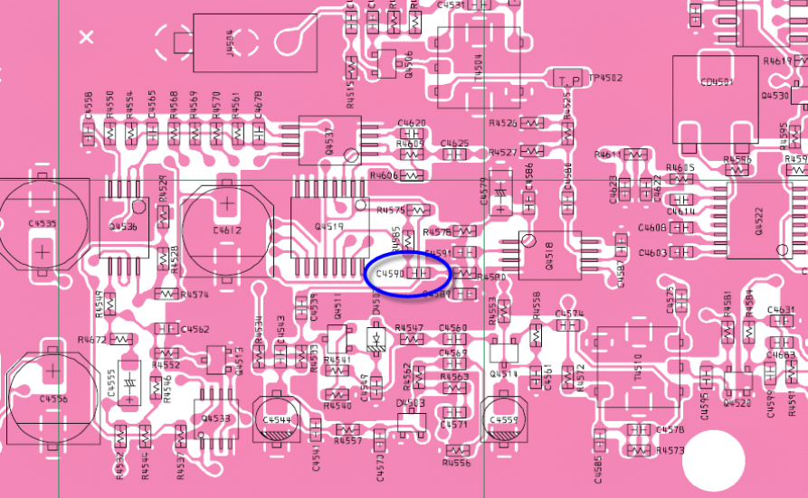
A Better Solution? - The 1K Filter ModThe roll-off mod detailed above works great in making the rig *sound* better. But it does not provide a meaningful amount of close-in selectivity. The roll-off is just too gentle. As speculated earlier, a better solution would be to try to work out a mod such that the narrower 1K filter in the CW-wide position. The benefit of using the narrower filter is that the low end would have a steep attenuation similar to what we enjoy with the narrow 300/500 Hz option. Adding a variable frequency multi-pole LPF filter on the AF output (located in the speaker?) - along with a 2-pole Q=10 bandpass filter to bring the APF would result in the sub having quite similar capabilities to the main receiver's DSP. A prerequisite to doing this mod is to have the ability to determine when the RX is in the CW mode. Unfortunately, there does not appear to be separate mode decode lines off of the serial to parallel link to the control board. There is a CW indicator on the VFD, which implies a matching CW line somewhere on the control board which could be routed for the purpose of switching the filter. Instead of hunting this down, I decided at the beginning to test the approach just to simply route both the 2.2 and 1.0 KHz filter switch lines together through a diode pair - such that they enable the 1.0 KHz filter in all cases. As a result, the 2.2 kHz filter is unused following the 1K Filter Mod. This turned out to be no significant compromise because the actual width measured of the 1KHz filter was closer to 2KHz! 1K Filter Mod - Surgery Road-mapThe mod involves cutting the two traces which lead to the darlington pair which drive the PIN diode switching. Then, adding a set of diodes which serve as an OR function - so that the 1KHz filter PIN diode line is pulled low with either a 1K or 2.2K signal from the upstream controller. Schematic follows. Note: Done carefully, this mod is fully reversible. Schematic Details for the 1K Filter Mod 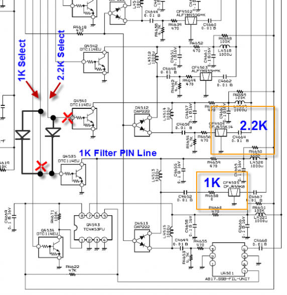
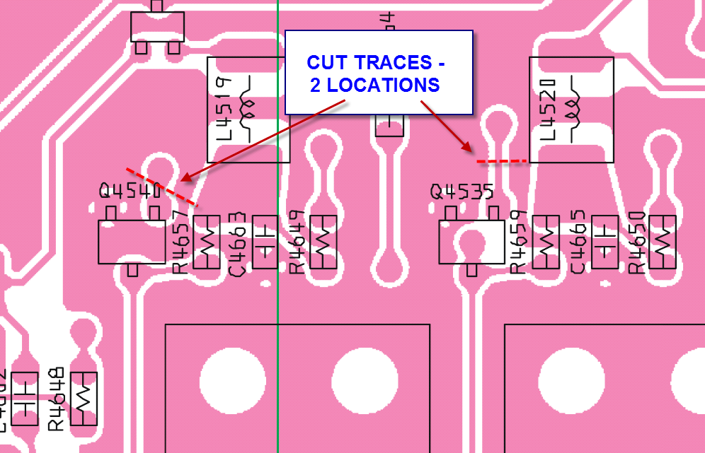
PCB preparation involves cutting the two traces indicated below. I used a very sharp x-acto blade. PCB Trace Cut Locations 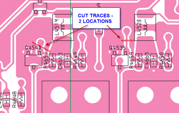
After testing the PCB cuts to ensure the traces were open and not inadvertently shorted to the surrounding ground trace, the pads were tinned and two 914 diodes trimmed and tinned. It's super important that any work done on the FT2K boards involve heating for the minimum amount of time necessary to prevent pad dalamination. The via connections and the base of the darlington provide natural mounting points. Diode Mounting Example 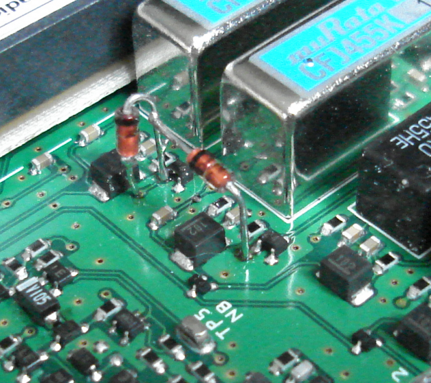
1K Filter Mod - Response GraphsAfter the mod, the total filter width is about 1 KHz less on all modes. The graph below shows the difference in responses between the Roll-off Mod and the 1K filter mod. Notice the low end attenuation skirts are steep in all modes with about 500 Hz of the low end trimmed - and an additional 500 Hz removed from the top end. Comparison of the 2.2 KHz width filter with Roll-off Mod - vs. - 1K Filter Mod (no Roll-off Mod) 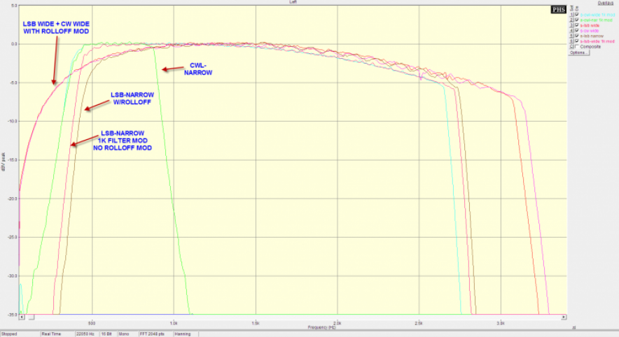
1K Filter Mod Results - Mode: SSBThe IF offset is individually trimmable. And the response of the sub and the main can be made very similar to the main receiver. The graph below compares the response of the main RX and modified sub. IF offset in this case was -120 Hz. Low end roll off starts about 250 Hz; high end about 2.6 KHz for a total width of about 2.4 KHz. The IF offset adjustment moves the entire curve left or right on the frequency spectrum allowing adjustment to personal preference. The same filter is used in either the SSB wide or SSB narrow position and as such, the responses are identical. Only the LSB is shown here. LSB: Main RX - vs. - Sub RX with 1K Mod 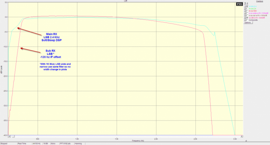
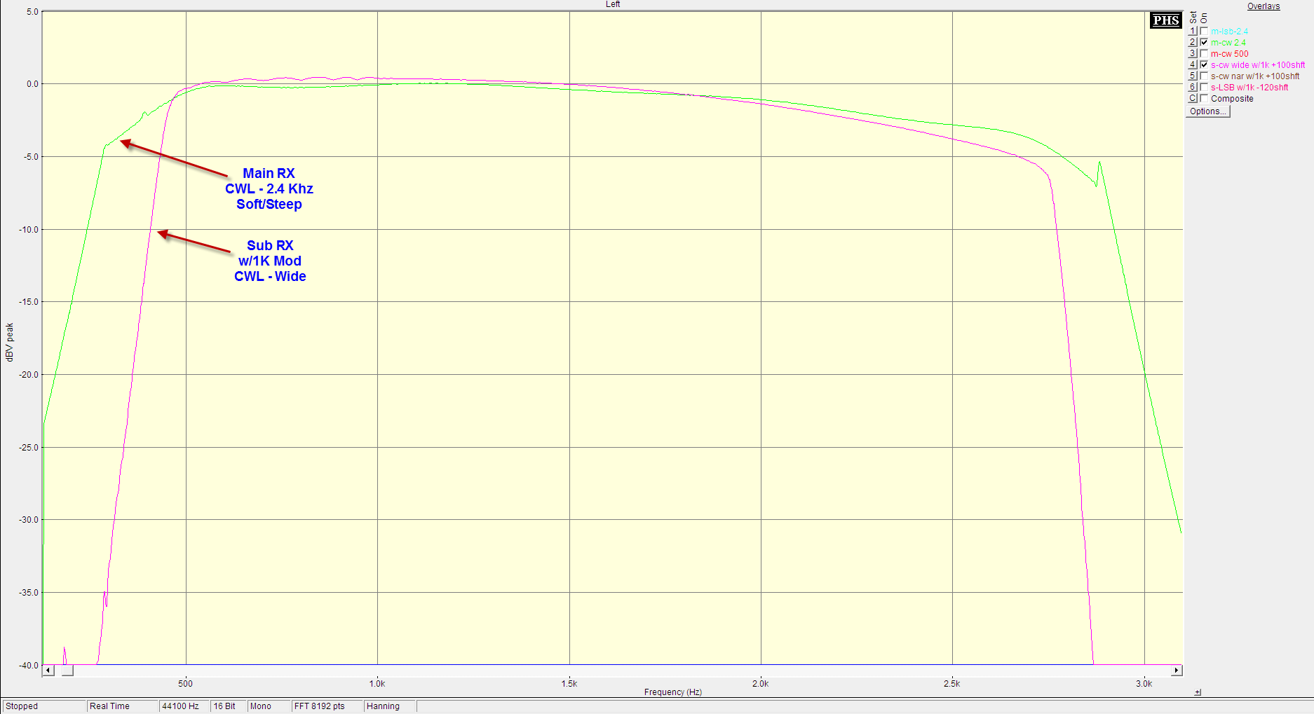
1K Filter Mod Results: Mode - CW WideWhen the DSP is set in the soft/steep position, the transition is more rounded than the sub receiver. The plot below compares the 2.4 KHz DSP default of the main receiver with the modified sub. IF offset in this case was +100 Hz. Less offset would provide more low end response shifting the entire curve to the left. Note that the IF shift applies to both the CW wide and CW narrow settings. CWL: WIDE - Main RX - vs. - Sub RX with 1K Mod 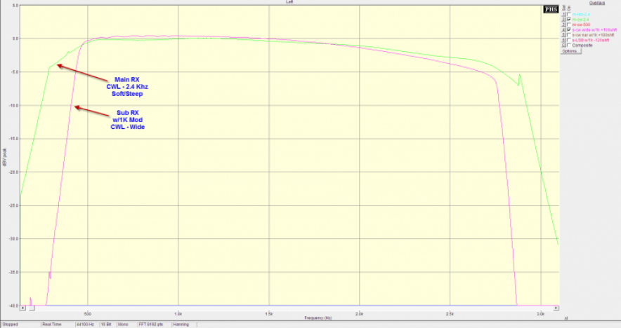
1K Filter Mod Results: Mode - CW NarrowThe filter in this rig is the Inrad 300 Hz model. In these tests, the width showed a bit higher - being closer to 500 Hz than 300. With a CW IF offset of +100 Hz, the response of the sub and the main receiver are almost identical. The steep skirts of the DSP stand out in comparison to the Inrad mechanical. CWL: NARROW - Main RX - vs. - Sub RX with 1K Mod 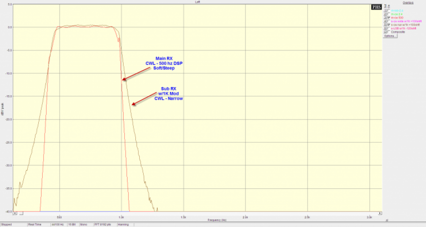
1K Filter Mod: Can We Have Variable Bandwidth Too?The 2nd IF filtering provides excellent low end selectivity. And the 300/500 Hz filter provides a good fixed with option with no further equipment or modifications required. One reason the low end service by the 2nd IF is so important is that, when implemented in an active filter, the group delay skew on the low side is about 3x that of the high side. Generally speaking, more group delay skew over the passband translates to more ringing. In this case, additional low end filtering is not needed. And with the addition of a switched capacitor LPF active filter between the rig's AF output and he speaker, a very close approximation of a variable bandwidth filter is achieved. The graph below estimates the response of an 8-pole butterworth response filter. To add the APF response, the active filter board would need just one more op amp to implement a Q=10 @ 600 Hz (or your favorite spot frequency) which would just be switched in series. By using a switched capacitor single-chip implementation, this filter would provide variable corner frequencies from 500-2.5 kHz with as few as two IC. I believe a 555 used as the clock source, followed by a MAX7420 may provide a workable solution. Amplification would be needed following the filtering to drive the speaker but both the amp and the filter could be mounted in the SP2000 enclosure. Note: For more details on these last two projects, click here: 100W Speaker Amp and The Ultimate Audio Filter 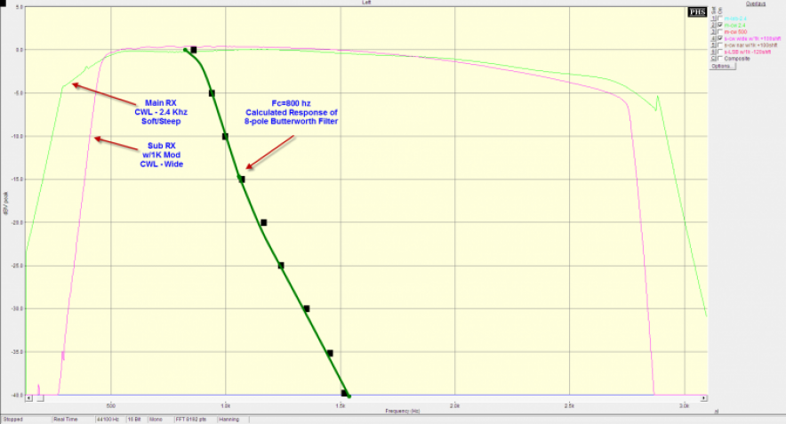
1K Filter Mod: ConclusionsI am very happy with the results of the 1K Filter Mod. It's easy to implement, reversible and provides an excellent low end stop. Used with the switchable 300/500 filter option, or with an active filter solution of some kind, true variable bandwidth low ringing response would be available. Adding an APF capability similar to the main RX would be easy as well. While I am curious as to why the 1K filter seems to behave so "wide", it ultimately works to advantage here in that the net passband is completely adequate for SSB use. MURATA DATA SHEET - The 1K filter is shown in yellow. 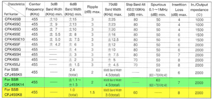
Future InvestigationsWith the 1K Filter Mod , three items remain on the to-do list...
- Add AF filtering to provide the APF response and a an adjustable LPF. Click HERE for more details...
- Find the source of the "hiss" of the receiver at low signal input conditions.
- Why is the 1K filter measuring nearly 2 KHz in testing? Point of curiosity...
|