The NS filter was designed to help the FT2K combat IMD products - and for that job, it's excellent. However, another topic of debate has come up recently - this time relating to the rigs' image rejection under one very special set of circumstances. And some speculation as to the NS filter's participation has been advanced. The following is an explanation of the effect - and some measurements taken on various filters which offer some insight. ISSUE and CONDITIONS REQUIREDA signal can be heard in the passband if all of the following are conditions are met. - A strong signal must be present and located exactly 900 KHz above from the rig's tuned frequency. For example, if you are listening at 14.000 MHz, the tone must be resident at 14.900 MHz
- The strong signal level must be about S9+30 or greater. The actual level seems to vary - some operators report being able to reproduce this with S9+20 signals; while others needed a S9+50 or stronger signal level.
- The 900 KHz strong signal and the tuned frequency must be found within a band range for the built-in preselector range.
- And lastly, no interference combating tools are enabled (so VRF off, uTune off, ATTN off)
VARIABLESThe strength of the signal hear at the tuned frequency is generally reported - with the conditions above - to be around S1. The signal strength varies with several factors, however. They are: - Roofing filter setting. In some cases, the Yaesu 6 KHz filter is reported to have the best performance (meaning no tone heard). In other cases, there seems to be no difference between the filters selected. And in other cases, the NS filter is reported to have the strongest tone.
- If the strong 900 KHz offset signal level is greater, the signal heard at the tuned frequency will be stronger as well. Which means that engaging the preamp - or using a directional antenna providing gain - will make the signal strength appear stronger.
- Lead lengths and wire dress of the NS filter installation play a factor here. I estimate this factor can make as much as a 15db difference in the effective attenuation provided by the filter at the 900 KHz offset - with shorter leads and better dress providing the better performance
- The antenna (and matching network including the use of the rig or external ATU) plays a factor beyond gain. As the operation frequency drops, the natural Q of the antenna/match combo is more significant and provides more natural attenuation to the 900 KHz signal. Which means, the better your antenna system is, the stronger the 900 KHz signal must be for you to hear it.
INSIDE THE RIGThis is basically an image rejection phenomenon. The rig has 3 mixers - and with the right combination of inputs, the product of these mixing operations can appear in the passband. And as a result, will be audible. In this case, what is happening inside the rig is: - The S9+30 strong signal at 900 KHz offset is presented at the 1st mixer output and fed to the roofing filter. The roofing filter provides attenuation to the mixed product - because it is 900 KHz removed from the tuned frequency and is out of the passband. The amount of attenuation will be typically 60-80 db, depending on the roofing filter selected and other factors [at attenuation levels this great, micro-sized variations in parts, tolerances, alignment, etc can affect the final attenuation level].
- The original 900 KHz signal comes from the roofing filter and is presented to the 2nd mixer along with whatever signals are in the intended passband. And because the 2nd IF is a 450 KHz design - the original 900 KHz signal will show up centered exactly in the passband of the 2nd if now, and pass through the 15 KHz filter in that stage.
- Finally, because the original 900 KHz offset signal is now in the center of the 450 KHz passband, none of the following stages filtering will affect the signal. And it can be heard in the AF output at roughly a S1 level
This is actually the proper operation of the receiver. At no point has an overload or other unintended non-linear operation has occurred. The strength of the final signal will be at a level roughly in line with the ultimate attenuation provided by the roofing filter. In this case, 60-80 db depending on various factors. Image rejection is an issue facing all superhet architechure to one extent or another. And for this reason, rig makers generally specify image rejection values in one blanket statement which is intended to cover all various combinations of conditions. The typical value is "70 db minimum." Yaesu is not alone in this 70db number - the K3, Orion II and IC7800, among others, all have a 70 db image rejection spec. PRESELECTOR RANGES As mentioned earlier, the 900 KHz signal must not be attenuated by any of the rigs other features. One feature which is not user-selectable is the preselector BPF module range. The frequency ranges are auto-selected based on the rig's current tune frequency. The preselector BPF ranges are: 1.7-2.5 MHz 3.4-4.7 Mhz 4.7-6.9 MHz 6.9-9.9 Mhz 9.9-13.9 Mhz 13.9-20.9 Mhz The effect of the preselector action is to further reduce the possible range of frequencies where an image can be detected under any circumstances. A CLOSER LOOK AT TWO ROOFING FILTERSTo understand what the normal expectation should be with respect to the 900 KHz image offset, I tested the Yaesu 69L2 6 KHz roofing filter and the NS 69.45 MHz roofing filter. The test frequency was set a 900 KHz above (first graph) and 900 KHz below (second graph) the filter 69.45 MHz center frequency. And a span of 50 KHz on each side of the 900 KHz offset point was plotted. And because these values are very close to the configuration noise floor, a plot of the noise floor was recorded. Stopband attenuation at +900 KHz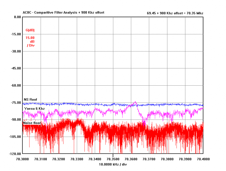
Stopband attenuation at -900 KHz 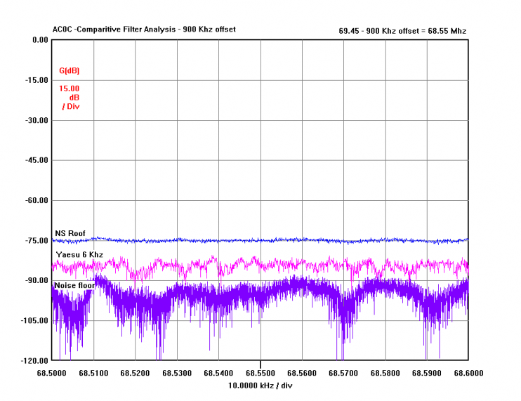
Observations: The Yaesu 6 KHz filter offers about 10 db more stopband attenuation compared to the NS filter at the 900 KHz offset point. There are slight variations in the 6 KHz plot which may be due to the filter characteristics - or because we are so close to the noise floor. Conclusion: Based on this 10 db measured stopband attenuation difference, we should expect the 6 KHz filter to offer about 10 db more image rejection than the NS filter under the same conditions. CONCLUSIONS in ACTUAL OPERATION So does this issue represent a problem in actual operation - meaning does it interfere with our QSO making capability? Clearly the answer is no. And here is why: - We need an interfering signal of S9+30 or stronger in amplitude, and
- The interfering signal must be located at exactly 900 KHz above from our QSO, and
- That 900 KHz offset frequency must not fall in a frequency range that is filtered automatically by the rig's BPF preselector, and
- The antenna system must be broadbanded, so that the signal level at the 900 KHz offset is not naturally attenuated by the antenna/match.
- Additionally, the strength of our desired station must be at a similar level as the image product - otherwise, the image can be ignored
- Finally, invoking some attenuation, the VRF, uTune or other roofing filters will further reduce or eliminate the image level
The fact is that there are many options available to the operator to address this case, should it ever give you a bit of trouble with your QSO. Just as knowing when to use a yagi or a dipole, applying the best tool for the job is part of the skill of being a good ham. Fortunately Yaesu has provided us with a great array of tools. And with the addition of the NS filter, these rigs are ready for serious work as the bands heat up - be that contesting, DX chasing or rag chewing. |